

Basics of Engineering Drawing by Zahid Ahmed Siddiqui full book pdf format.


Click Here to download the book.
Introduction One of the best ways to communicate one’s ideas is through some form of picture or drawing. This is especially true for the engineer. The purpose of this guide is to give you the basics of engineering sketching and drawing.
We will treat “sketching” and “drawing” as one. “Sketching” generally means freehand drawing. “Drawing” usually means using drawing instruments, from compasses to computers to bring precision to the drawings.
This is just an introduction. Don’t worry about understanding every detail right now - just get a general feel for the language of graphics.
We hope you like the object in Figure 1, because you’ll be seeing a lot of it. Before we get started on any technical drawings, let’s get a good look at this strange block from several angles.
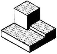 Figure 1 - A Machined Block.
Isometric Drawing The representation of the object in figure 2 is called an isometric drawing. This is one of a family of three-dimensional views called pictorial drawings. In an isometric drawing, the object’s vertical lines are drawn vertically, and the horizontal lines in the width and depth planes are shown at 30 degrees to the horizontal. When drawn under these guidelines, the lines parallel to these three axes are at their true (scale) lengths. Lines that are not parallel to these axes will not be of their true length.
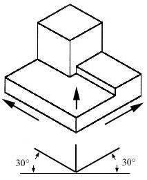
Figure 2 - An Isometric Drawing.
Any engineering drawing should show everything: a complete understanding of the object should be possible from the drawing. If the isometric drawing can show all details and all dimensions on one drawing, it is ideal. One can pack a great deal of information into an isometric drawing. However, if the object in figure 2 had a hole on the back side, it would not be visible using a single isometric drawing. In order to get a more complete view of the object, an orthographic projection may be used.
Orthographic or Multiview Drawing Imagine that you have an object suspended by transparent threads inside a glass box, as in figure 3.
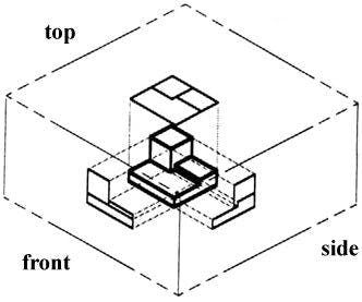 Figure 3 - The block suspended in a glass box.
Then draw the object on each of three faces as seen from that direction. Unfold the box (figure 4) and you have the three views. We call this an “orthographic” or “multiview” drawing.
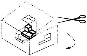
Figure 4 - The creation of an orthographic multiview drawing.
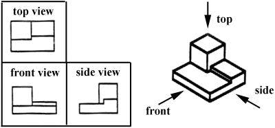
Figure 5 - A multiview drawing and its explanation.
Which views should one choose for a multiview drawing? The views that reveal every detail about the object. Three views are not always necessary; we need only as many views as are required to describe the object fully. For example, some objects need only two views, while others need four. The circular object in figure 6 requires only two views.
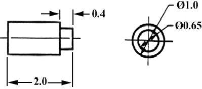 Figure 6 - An object needing only two orthogonal views.
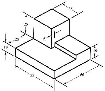 Figure 7 - An isometric view with dimensions.
We have “dimensioned” the object in the isometric drawing in figure 7. As a general guideline to dimensioning, try to think that you would make an object and dimension it in the most useful way. Put in exactly as many dimensions as are necessary for the craftsperson to make it -no more, no less. Do not put in redundant dimensions. Not only will these clutter the drawing, but if “tolerances” or accuracy levels have been included, the redundant dimensions often lead to conflicts when the tolerance allowances can be added in different ways.
Repeatedly measuring from one point to another will lead to inaccuracies. It is often better to measure from one end to various points. This gives the dimensions a reference standard. It is helpful to choose the placement of the dimension in the order in which a machinist would create the part. This convention may take some experience.
Sectioning There are many times when the interior details of an object cannot be seen from the outside (figure 8).
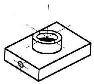 Figure 8 - An isometric drawing that does not show all details.
We can get around this by pretending to cut the object on a plane and showing the “sectional view”. The sectional view is applicable to objects like engine blocks, where the interior details are intricate and would be very difficult to understand through the use of “hidden” lines (hidden lines are, by convention, dotted) on an orthographic or isometric drawing.